UML
Class Diagrams
Introduction
What 
🏆 Can explain/identify class diagrams ![]()
UML class diagrams describe the structure (but not the behavior) of an OOP solution. These are possibly the most often used diagrams in the industry and an indispensable tool for an OO programmer.
{Give some example class diagrams here}
Classes
What 
🏆 Can draw a UML class ![]()
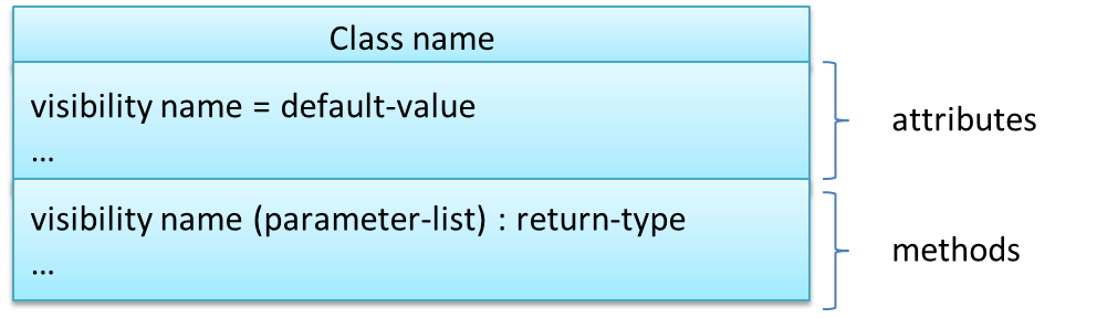
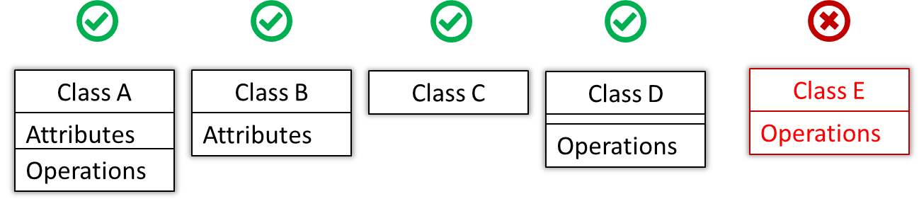
The above illustrates the basic notations of a class diagram: attributes represent the data of the class; methods represent the operations (or behavior).
Example:
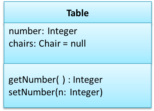
The ‘Operations’ compartment (or even both ‘Attributes’ and ‘Operations’ compartments) may be omitted if such details are not important for the task at hand.
Example:
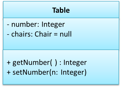
The visibility of attributes and operations is used to indicate the level of access allowed for each attribute or operation. The types of visibility and their exact meanings depend on the programming language used. Here are some common visibilities and how they are indicated in a class diagram:
- + public
- - private
- # protected
- ~ package
Associations
Basic
🏆 Can interpret simple associations in a class diagram ![]()
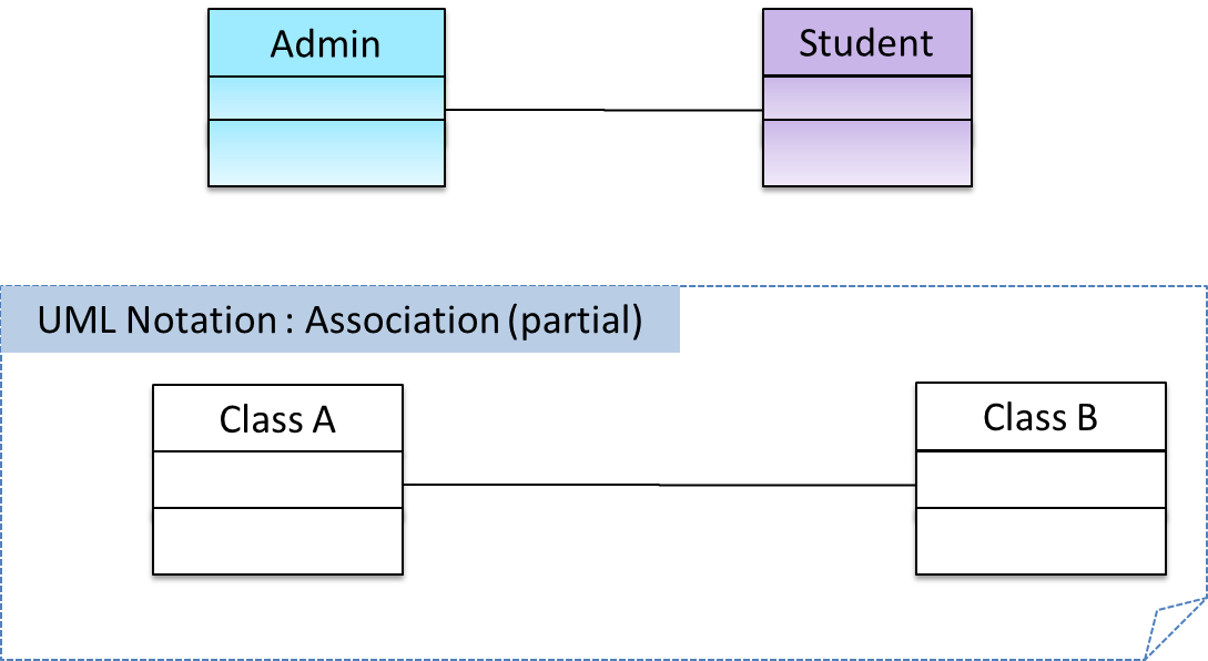
We use a solid line to show an association between two classes.
Navigability
🏆 Can interpret association navigabilities in class diagrams ![]()
We use arrow heads to indication the navigability of an association.
Logic is aware of Minefield, but Minefield is not aware of Logic
Roles
🏆 Can explain/use association roles in class diagrams ![]()
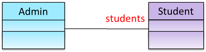
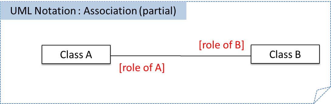
‘Role’ labels are optionally used to indicate the role played by the classes in the association.
Example:
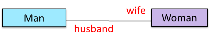
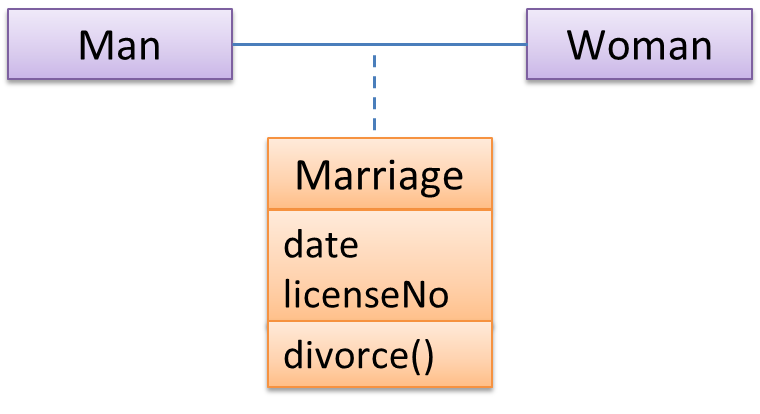
This association represents a marriage between a Man object and a Woman object. The respective roles played by objects of these two classes are husband and wife.
Example:
Labels
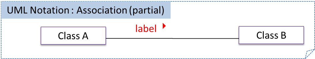
🏆 Can explain/use association labels in class diagrams ![]()
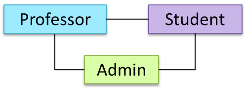
Association labels describe the association. The arrow head indicates the “direction” in which the label is to be read.
Example:
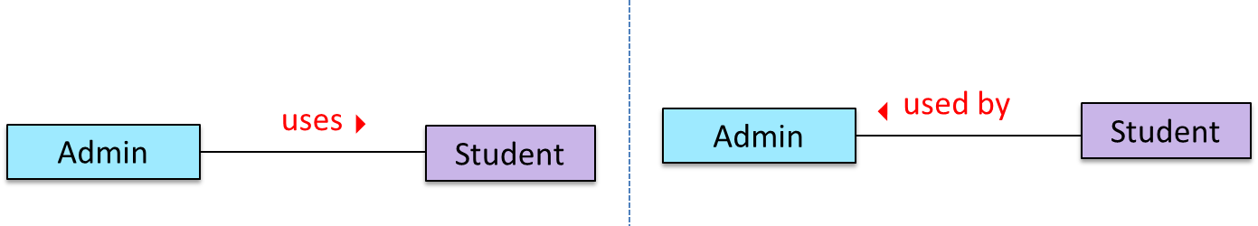
an Admin object uses Student objects” or “Student objects are used by an Admin object”.
Multiplicity
🏆 Can explain what is the multiplicity of an association ![]()
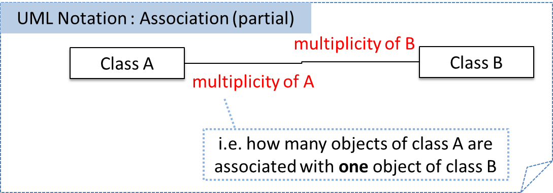
A class diagram can also indicate the multiplicity of an association. Multiplicity is the number of objects of a class that participate in the association.
Commonly used multiplicities:
- 0..1 : optional, can be linked to 0 or 1 objects
- 1 : compulsory, must be linked to one object at all times.
-
- : can be linked to 0 or more objects.
- n..m : the number of linked objects must be n to m inclusive
In the diagram below, an Admin object administers (in charge of) any number of students but a Student object must always be under the charge of exactly one Admin object
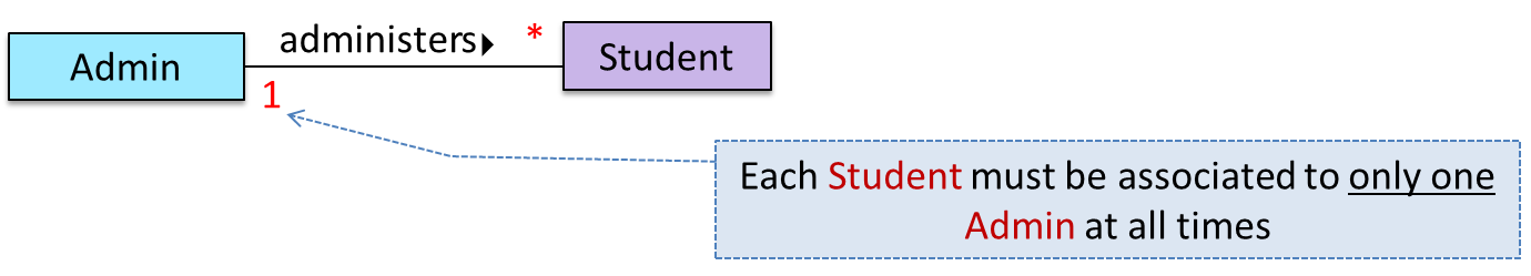
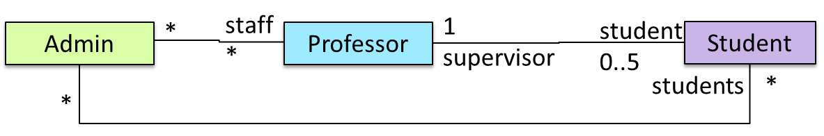
Example:
- Each Student must be supervised by a Professor.
- Students have matriculation numbers. A Professor cannot supervise more than 5 students.
- Admin staff handles Professors as well.
Dependencies
What 
🏆 Can interpret dependencies in a class diagram ![]()
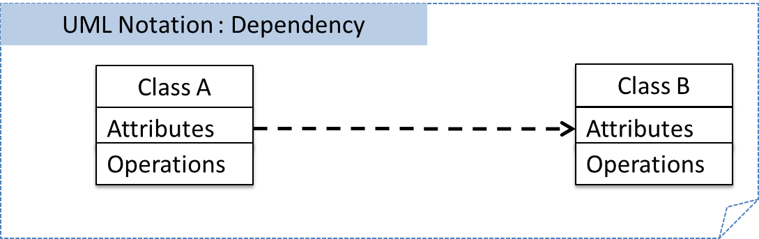
We use a dashed arrow to show dependencies.
Associations as Attributes
What
🏆 Can show an association as an attribute ![]()
An attribute is sometimes used to represent an association. The diagram below depicts a multiplayer Square Game being played on a board comprising of one hundred squares. Each of the squares may be occupied with any number
of Pieces, each belonging to a certain player. A piece may or may not be on a square. Note how the association ’is on’ can be replaced by an isOn attribute of the Piece class. In order to realize
the 0..1 multiplicity, the isOn attribute can either be null or hold a reference to a Square object.
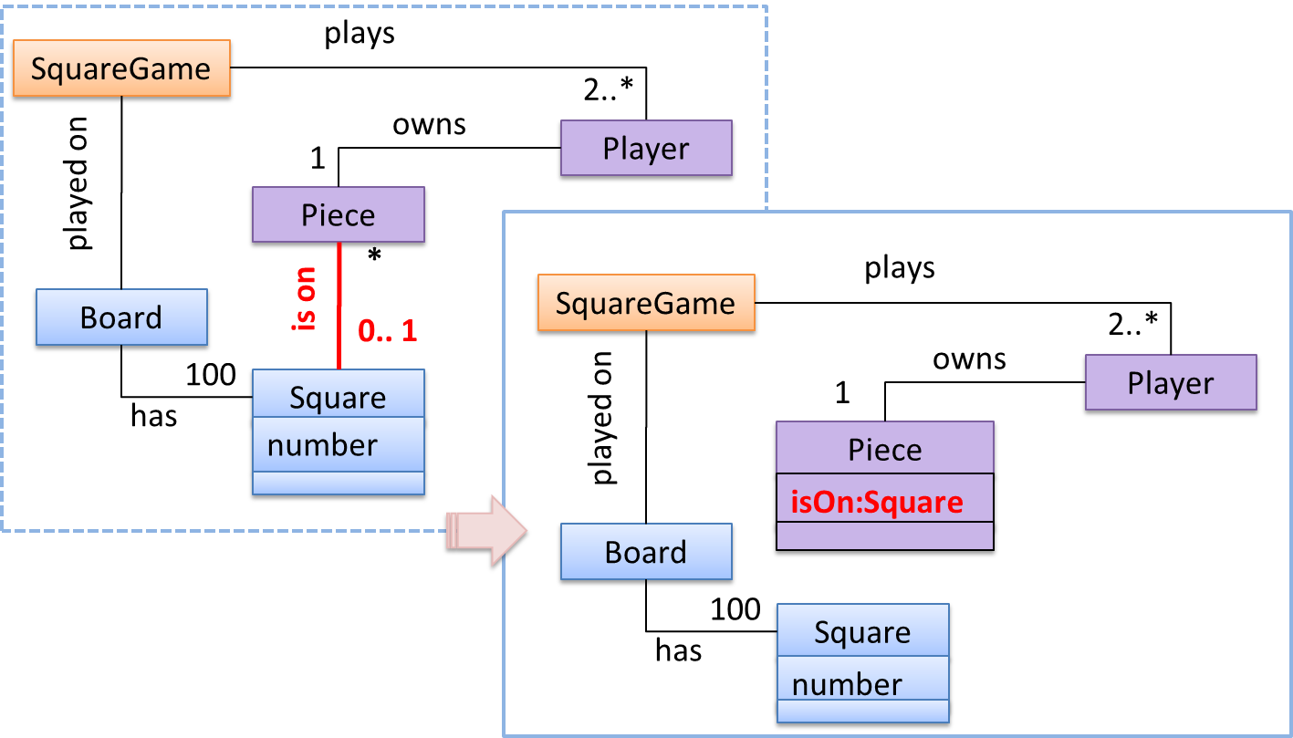
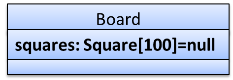
In addition, association multiplicities of two or more can be made as part of the attribute using
- name: type [multiplicity] = default value
Enumerations
What
🏆 Can interpret enumerations in class diagrams ![]()
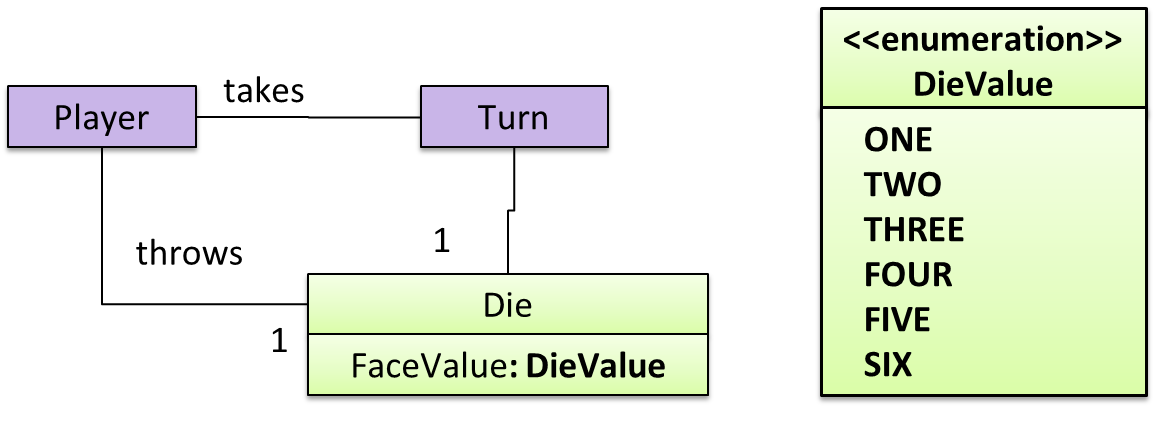
An << enumeration >> is used to indicate that an attribute can only take on a fixed set of values.
Example:
Class Level Members
What
🏆 Can interpret class-level members in class diagrams ![]()
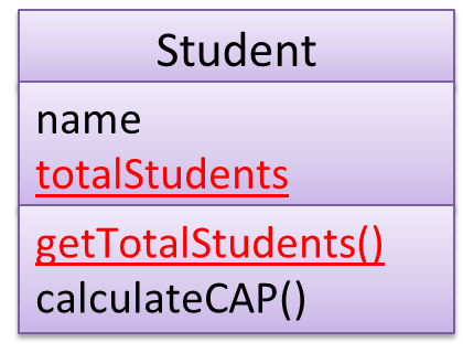
In UML class diagrams, underlines are used to denote class-level attributes and variables.
Example:
Association Classes
What
🏆 Can interpret association classes in class diagrams ![]()
Association classes are denoted as a connection to an association link using a dashed line as shown below.
Example:
Composition
What
🏆 Can interpret composition in class diagrams ![]()
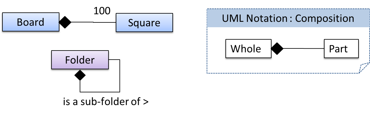
We use a solid diamond symbol to denote composition.
Example:
Aggregation
What
🏆 Can interpret aggregation in class diagrams ![]()
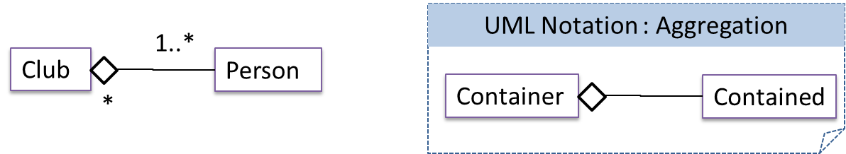
We use a hollow diamond is used to indicate an aggregation.
Example:
Class Inheritance
What
🏆 Can interpret class inheritance in class diagrams ![]()
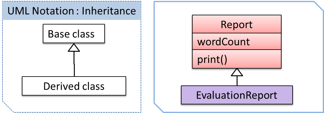
We uses a triangle and a solid line (not to be confused with an arrow) to indicate class inheritance.
Example:
Interfaces
What
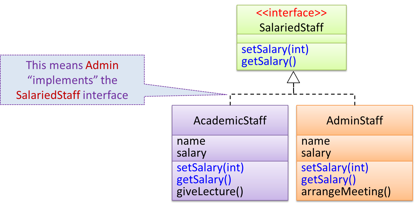
🏆 Can interpret interfaces in class diagrams ![]()
We use the keyword << interface >> to indicate an interface. Interface inheritance is shown similar to class inheritance except a dashed line is used instead of a solid line.
Example:
Abstract Classes
What
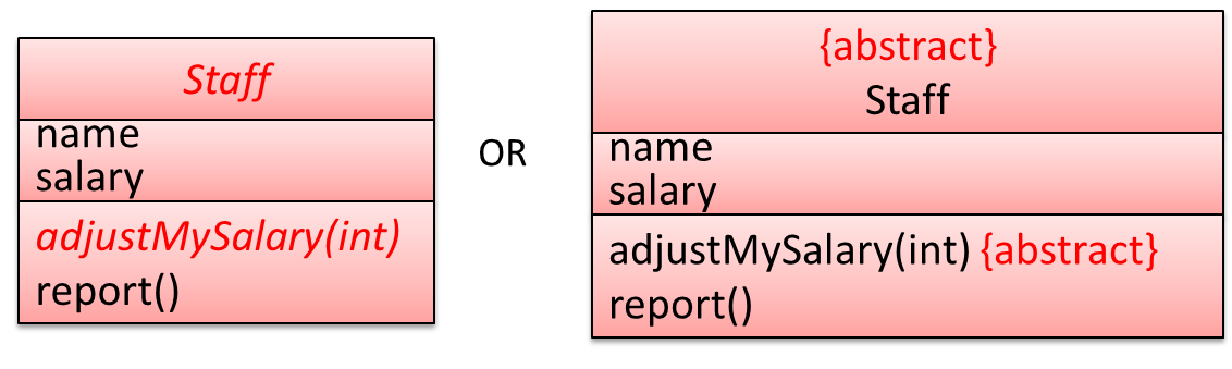
🏆 Can interpret abstract classes in class diagrams ![]()
We can use italics or {abstract} keyword to denote abstract classes/methods.

Example:
Sequence Diagrams
Introduction
🏆 Can explain/identify sequence diagrams ![]()
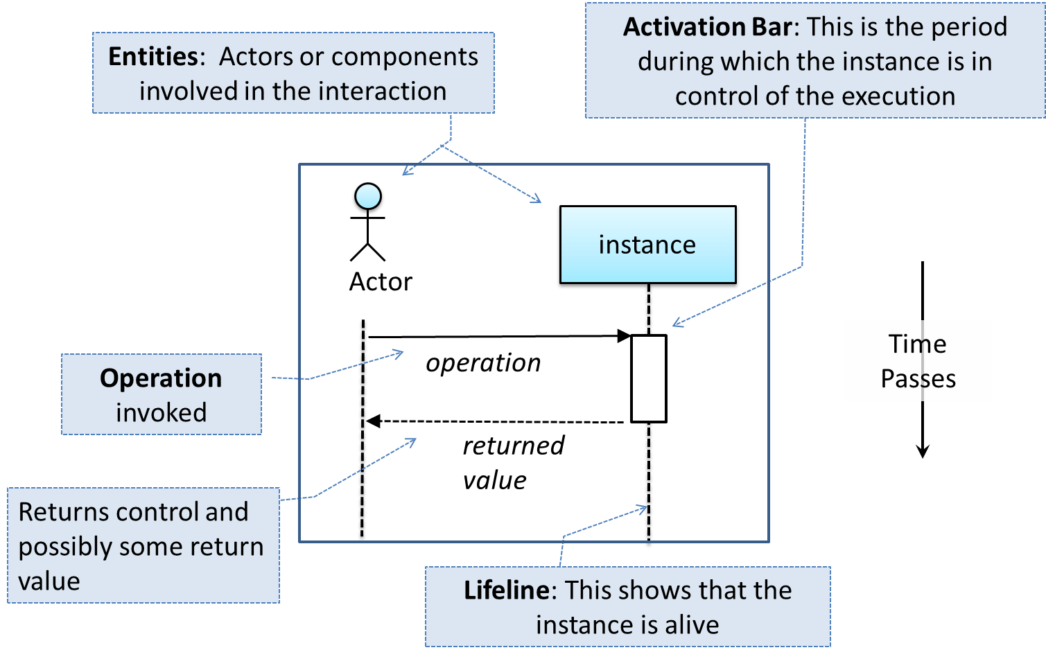
A UML sequence diagram captures the interactions between multiple objects for a given scenario.
Examples:
Basic
🏆 Can interpret sequence diagrams with basic notation ![]()
Notation:
Example:
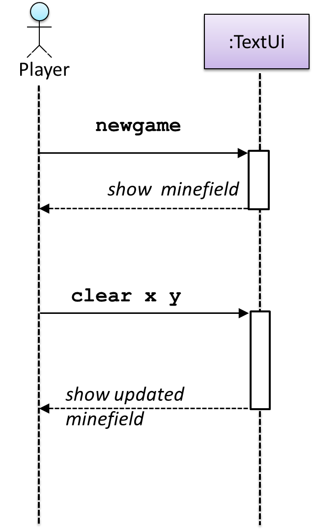
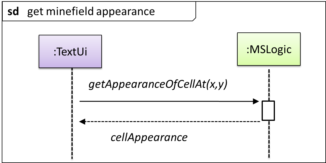
The notation :TextUi denotes ‘an unnamed instance of the class TextUi’. If there were two instances of TextUi in the diagram, they can be distinguished by naming them as TextUi1:TextUi and TextUi2:TextUi.
Object Creation
🏆 Can interpret sequence diagrams with object creation ![]()
Notation:
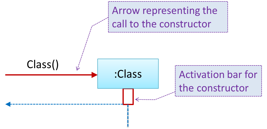
- The arrow that represents the constructor arrives at the side of the box representing the instance.
- The activation bar represents the period the constructor is active.
Example:

Object Deletion
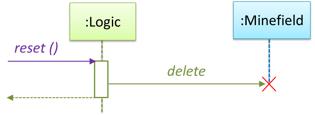
🏆 Can interpret sequence diagrams with object deletion ![]()
In languages such as Java that supports automatic memory management, although object deletion is not that important, the above notation can still be used to show the point at which the object ceased to be used.
Notation:

Example:
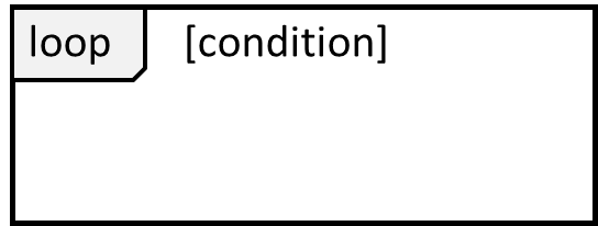
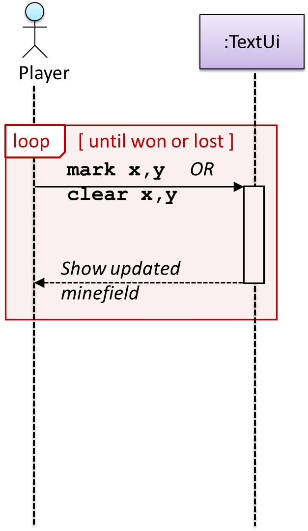
Loops
🏆 Can interpret sequence diagrams with loops ![]()
Notation:
Example:
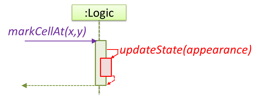
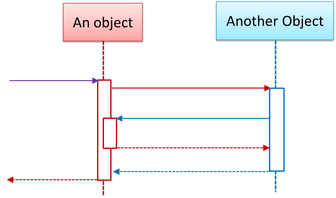
Self Invocation
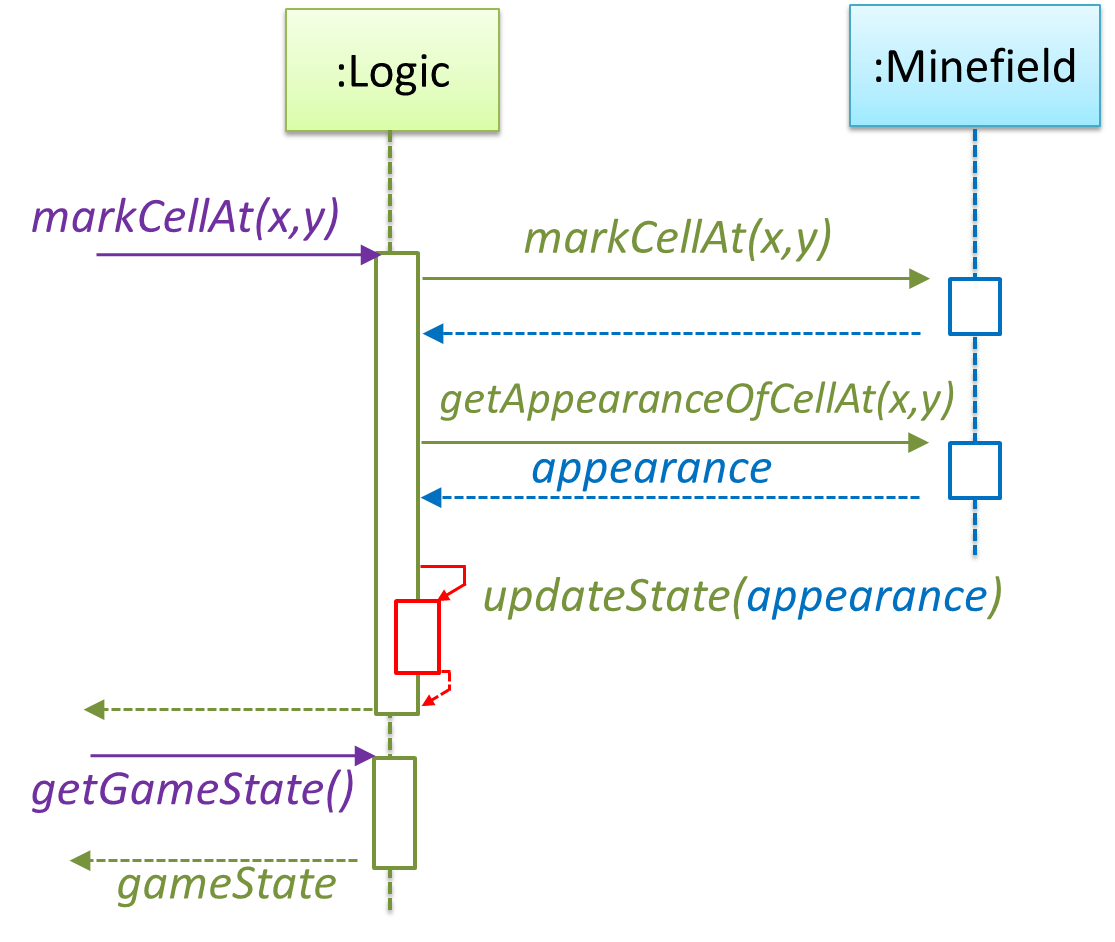
🏆 Can interpret sequence diagrams with self invocation ![]()
This is how we show a method of an object calling another method of the same object.
Notation:
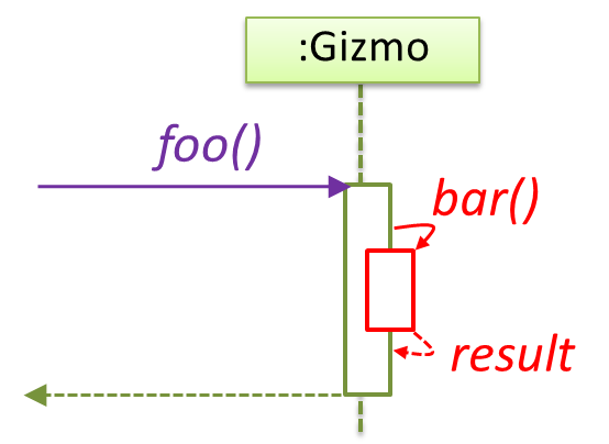
Example:
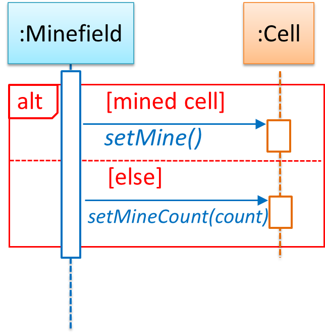
Alternative Paths
🏆 Can interpret sequence diagrams with alternative paths ![]()
We use alt frames to indicate alternative paths.
Notation:
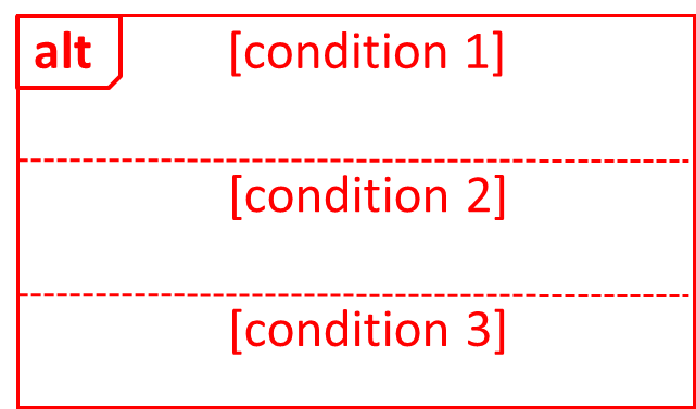
Example:
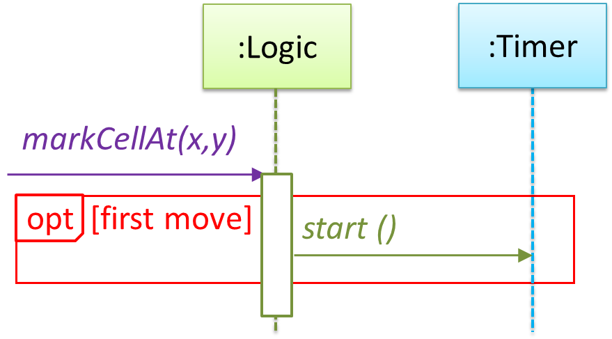
Optional Paths
🏆 Can interpret sequence diagrams with optional paths ![]()
We use opt frames to indicate optional paths.
Notation:

Example:
Parallel Paths
🏆 Can interpret sequence diagrams with parallel paths ![]()
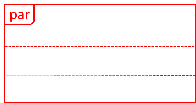
We use par frames to indicate parallel paths.
Notation:
Example:
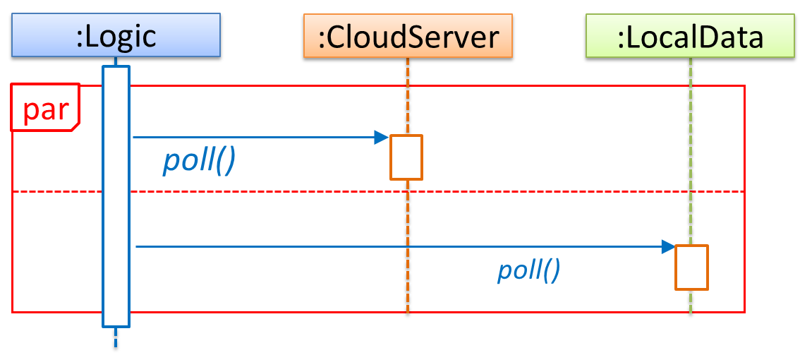
In this example Logic is polling both CloudServer and LocalServer objects in parallel.
Reference Frames
🏆 Can interpret sequence diagrams with reference frames ![]()
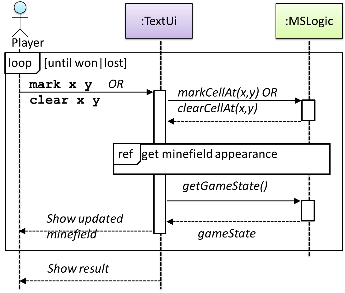
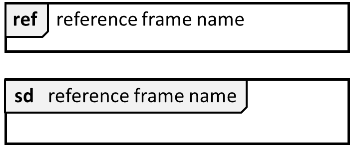
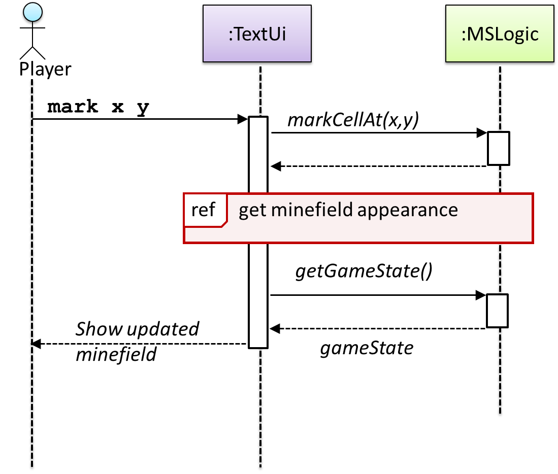
We use a ref frame to allow a segment of the interaction to be omitted and detailed in another diagram.
Notation:
Example:
Minimal Notation
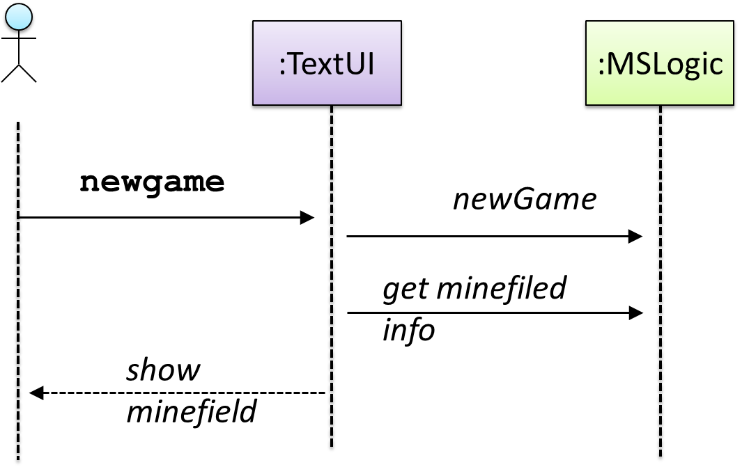
🏆 Can interpret sequence diagrams with minimal notation ![]()
To reduce clutter, activation bars and return arrows may be omitted if they do not result in ambiguities or loss in information. Informal operation descriptions such as those given in the SD below can be used, if the purpose is to brainstorm and not to specify the API.
Example:
Object Diagrams
Introduction
🏆 Can explain the purpose of UML object diagrams ![]()
An object diagram shows an object structure at a given point of time.
Objects
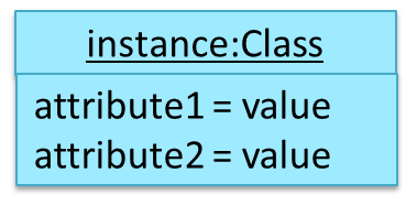
🏆 Can interpret objects shown in UML notation ![]()
Notation:
Example:
Object Structures
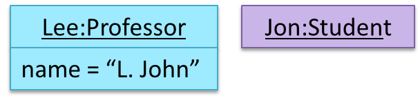
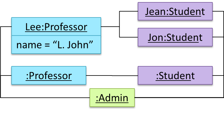
🏆 Can interpret object diagrams ![]()
Notation:
Example:
Activity Diagrams
Introduction
Alternate Paths
🏆 Can explain activity diagrams ![]()
Workflows define the flow or a connected sequence of steps in which a process or a set of tasks is executed. Understanding the workflow of the problem domain is important if the problem that is to be solved is connected to the workflow.
A UML Activity diagram (AD) can model workflows.
Basic Notations
Linear Paths
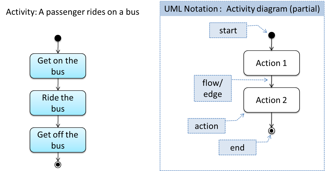
🏆 Can use linear paths in activity diagrams ![]()
An activity diagram (AD) consists of a sequence of actions and control flows. An action is a single step in an activity. It is shown as a rectangle with rounded edges. A control flow shows the flow of control from one action to the next. It is shown by drawing a line with an arrow-head to show the direction of the flow.
Alternate Paths
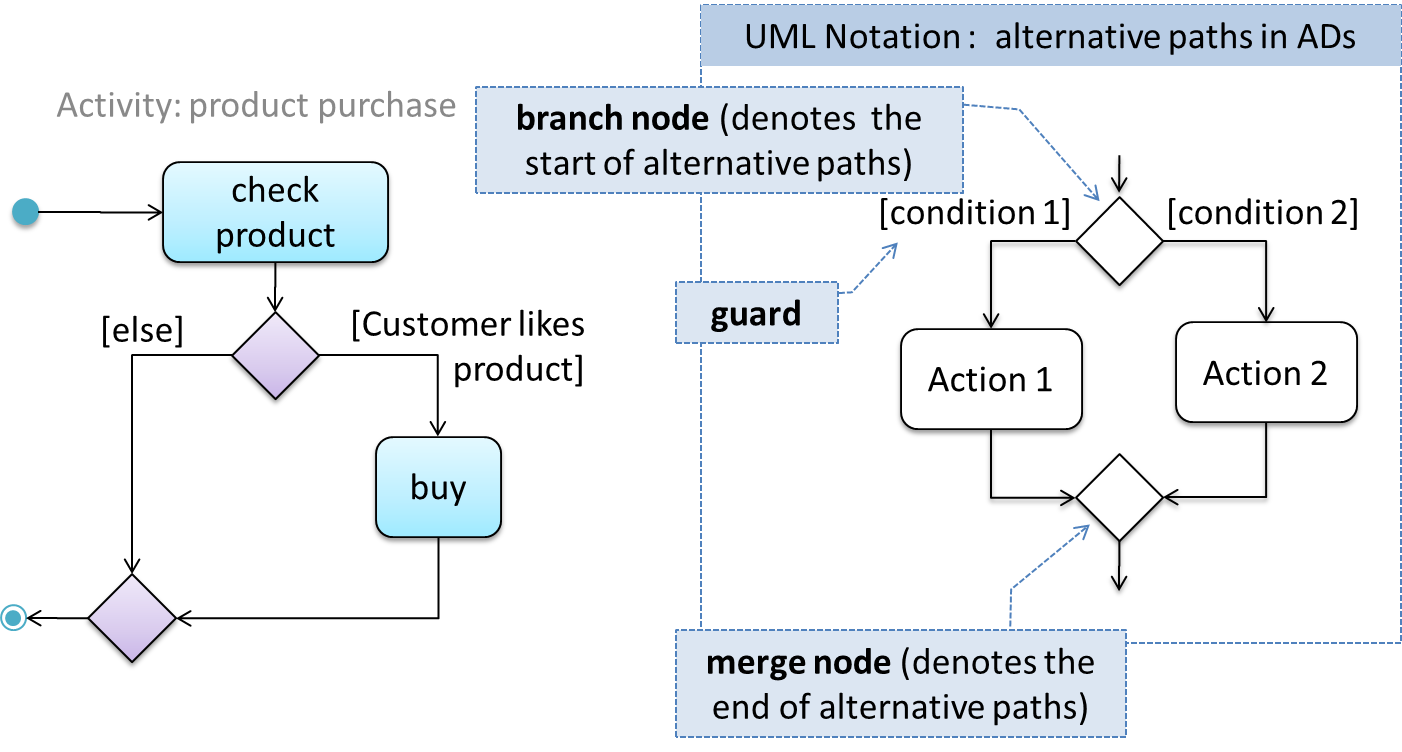
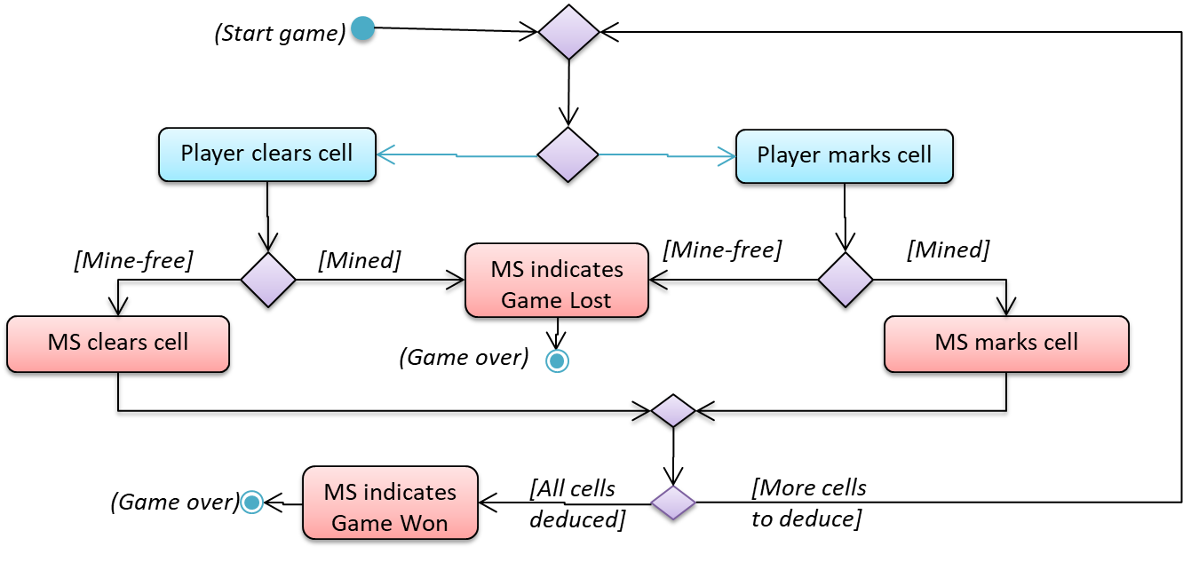
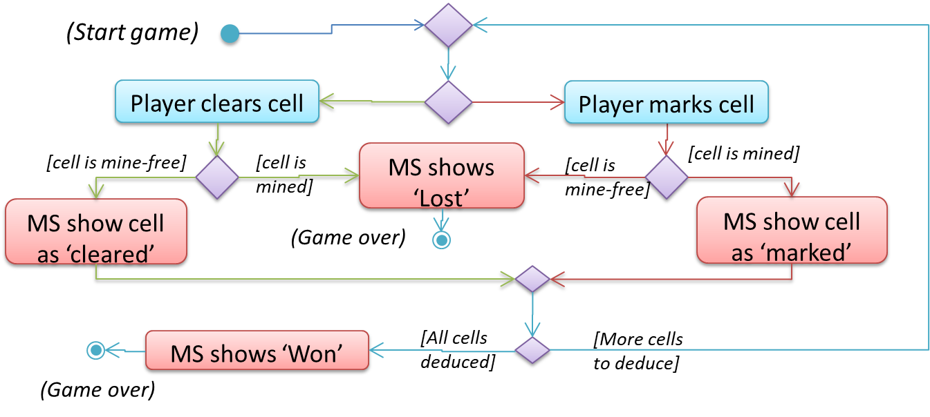
🏆 Can use alternate paths in activity diagrams ![]()
Branch nodes and merge nodes have the same notation: a diamond shape. They are used to show alternative (not parallel) paths through the AD. Each control flow exiting a Branch node has a guard condition which allows control to flow only if the guard condition is satisfied. Therefore, a guard is a boolean condition that should be true for execution to take a specific path.
Example: AD for the Minesweeper (MS) that shows actions done by the player and the game (MS).
Parallel Paths
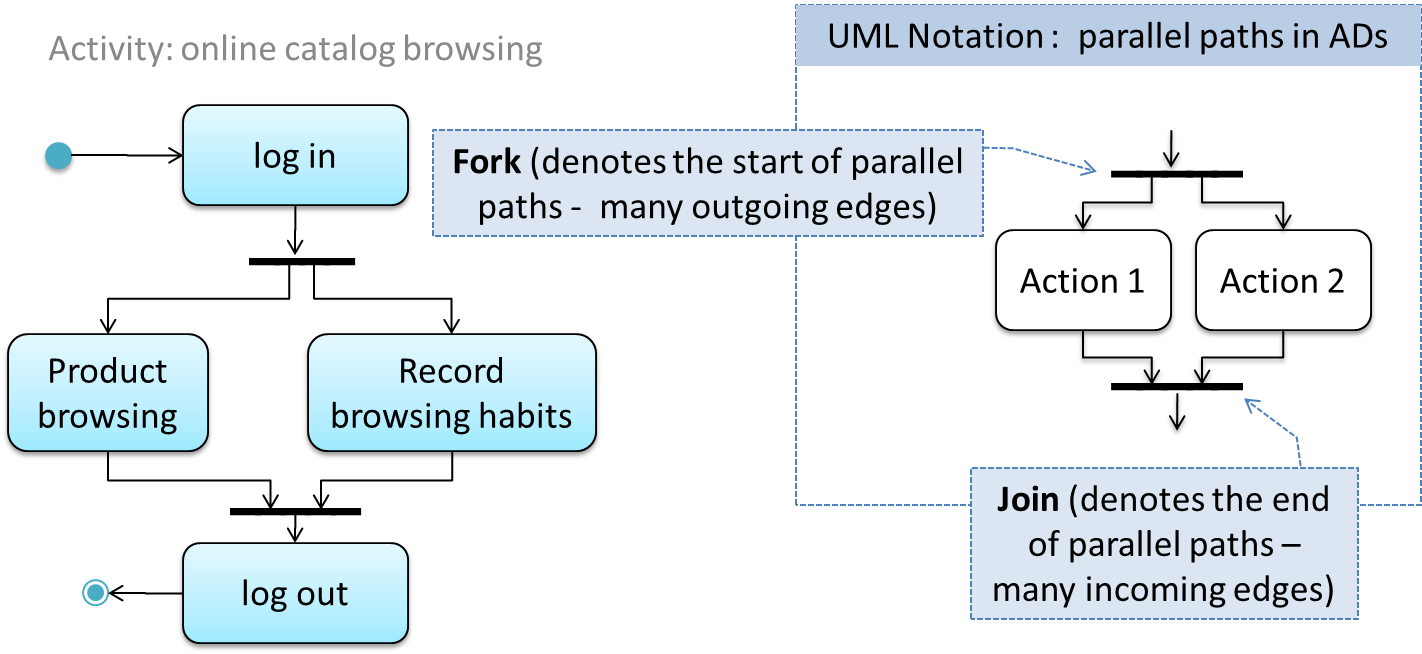
🏆 Can use parallel paths in activity diagrams ![]()
Forks and joins have the same notation: a bar. They indicate the start and end of concurrent flows of control. The following diagram shows an example of their use. For join, execution along all incoming control flows should be complete before the execution starts on the outgoing control flow.
Rakes
🏆 Can use rakes in activity diagrams ![]()
Here is the AD for a game of ‘snakes and ladders’.
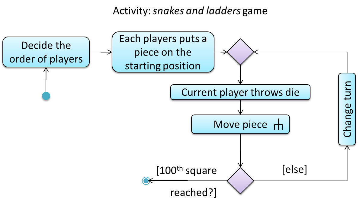
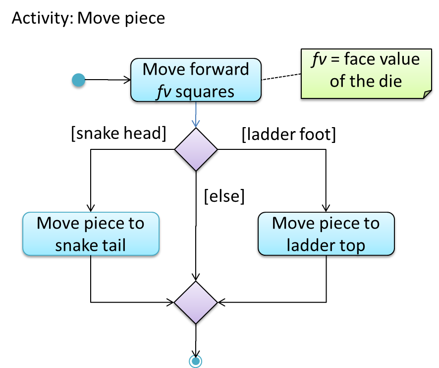
The rake symbol (in the “Move piece” action above) is used to show that an action is described in another subsidiary activity diagram elsewhere. That diagram is given below.
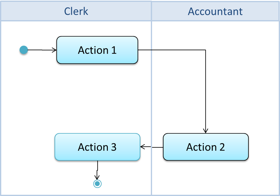
Swimlanes 
🏆 Can explain swimlanes in activity diagrams ![]()
It is possible to partition an activity diagram to show who is doing which action. Such partitioned activity diagrams are sometime called swimlane diagrams.
Note: Only essential elements of ADs are covered in this handout.
Combined
🏆 Can use basic activity diagram notations ![]()
Given below is the high-level game logic of the Minesweeper, drawn from the point of view of the player.
Incorporate the following new features to the above AD.
(a) timing
Description: The game keeps track of the total time spent on a game. The counting starts from the moment the first cell is cleared/marked and stops when the game is won or lost. Time elapsed is shown to the player after every mark/clear operation.
(b) standing_ground
Description: At the beginning of the game, the player chooses five cells to be revealed without penalty. This is done one cell at a time. If the cell so selected is mined, it will be marked automatically. The objective is to give some “standing ground” to the player from which he/she can deduce remaining cells. The player cannot mark or clear cells until the standing ground is selected.
(c) tolerate
Description: Marking a cell incorrectly is tolerated as long as the number of cells does not exceed the total mines. Marked cells can be unmarked. The player is not allowed to mark more cells if the total number of marked cells equals the total number of mines.
(a) No change to the AD
After incorporating (b)
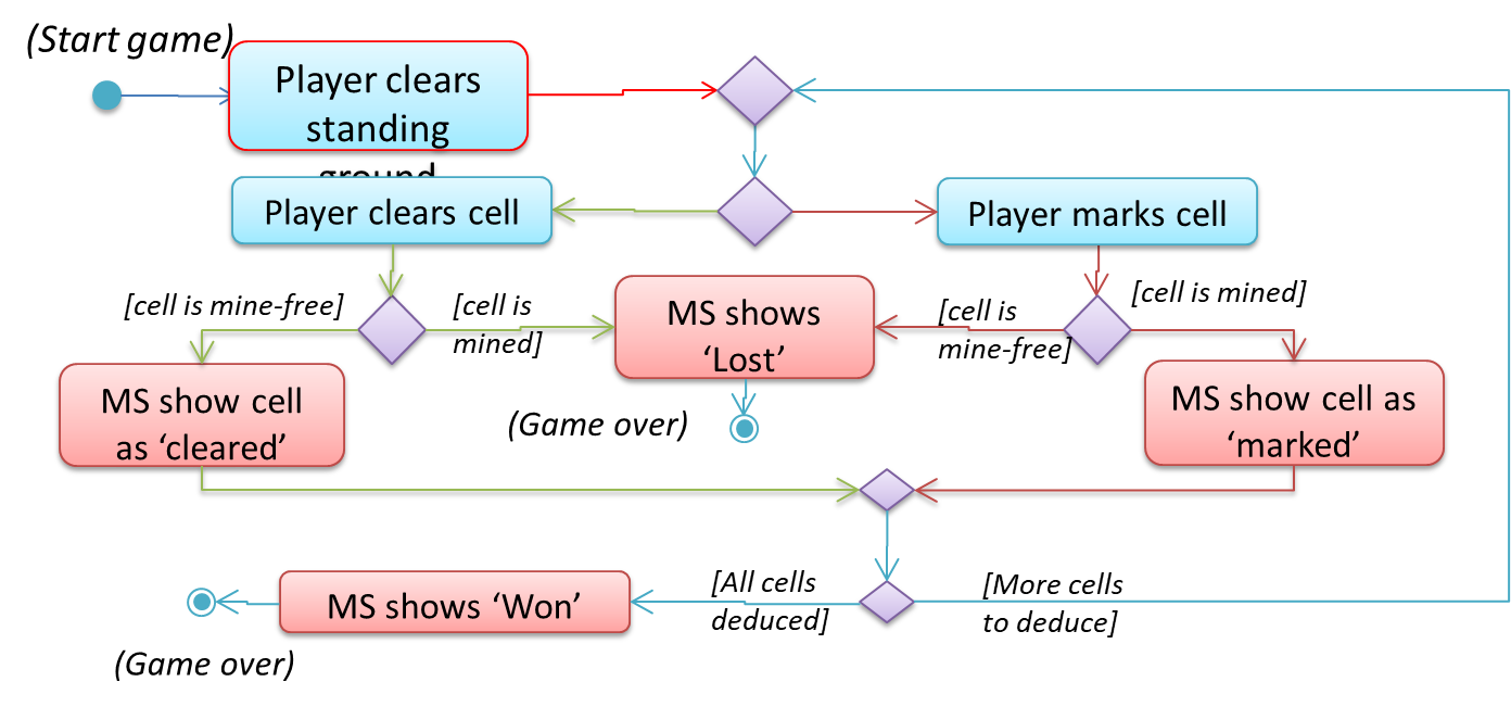
Given above is a minimal change. It is OK to show more details of the ‘clear standing ground’ action or show it as a separate AD.
After incorporating (c)
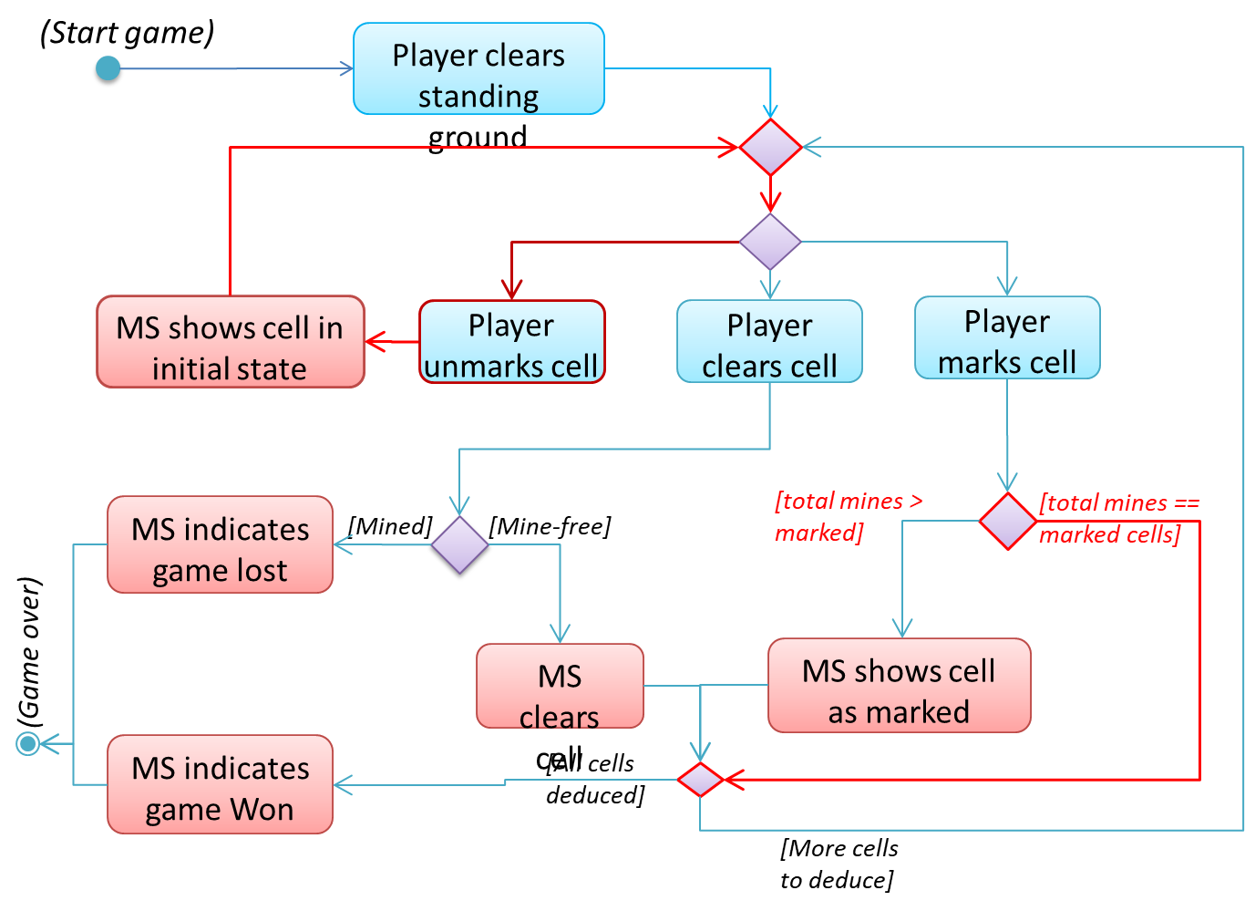
Note that some actions/paths have been deleted. The above diagram uses a diamond as either a branch or a merge (but not both). It is ok to use a diamond as both a merge and branch, as long as it does not lead to ambiguities.
Notes
Notes
🏆 Can use UML notes ![]()
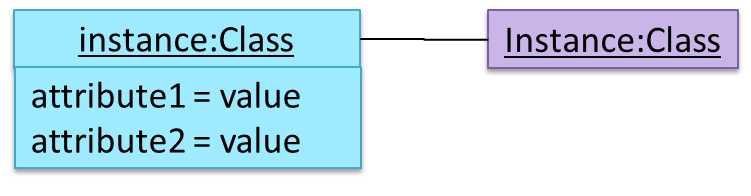
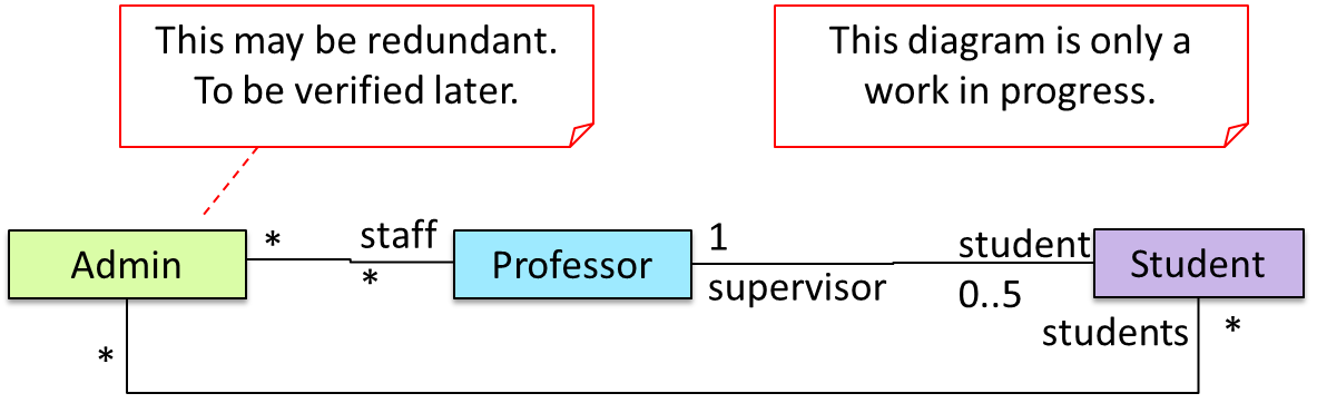
UML notes are used to augment a UML diagram with additional information. These notes can be shown connected to a particular element in the diagram or can be shown without a connection. The diagram below shows examples of both.
Constraints
🏆 Can specify constraints in UML diagrams ![]()
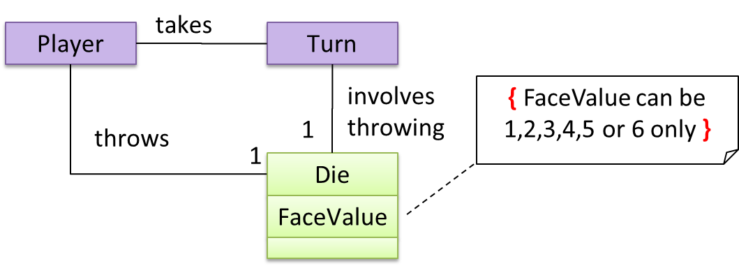
A note can be used to specify a constraintwithin curly brackets. Natural language or a formal notation such as OCL (Object Constraint Language) may be used to specify constraints. OCL is beyond the scope of this handout.
Miscellaneous
Object vs Class Diagrams
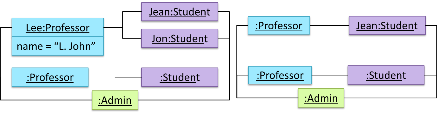
🏆 Can distinguish between class diagrams and object diagrams ![]()
Compared to the notation for a class diagrams, object diagrams differ in the following ways:
- Instance name may be shown
- There is a
:before the class name - Instance and class names are underlined
- Methods are omitted
- Multiplicities are omitted
Both object diagrams are derived from the same class diagram shown earlier. In other words, each of these object diagrams shows ‘an instance of’ the same class diagram.
Examples: